IPv4 Addresses, Routing and Subnet Masks
- Mia Combeau
- Network | Internet
- November 17, 2022
Table of Contents
IPv4 addresses are the most common on the Internet. How can they uniquely identify every connected object? How do they facilitate data routing from one side of this vast network to the other? And why are they progressively being replaced by IPv6 addresses? We will attempt to answer these questions in this article.
But before that, it wouldn’t be a bad idea to remind ourselves of the physical components of the Internet, which we’ve already taken a look at in the previous article on the Internet’s architecture.
The Internet’s Hardware
Internet is a global network with a staggering scale, composed of thousands of public and private networks, and millions of connected devices. Data flows through varied physical media, from coaxial cables to optical fiber to radio waves. It passes through switches and routers to finally arrive at the appropriate host’s network interface. Let’s define these terms here.
Hosts, Clients and Servers
A host is any system connected to the network. It might be a client or a server. A client is a computer, a smartphone, or some other type of connected device. A server is a more powerful machine which stores and distributes content over the Internet.
Packets
The sending host encapsulates the data to send into one or more packets. These packets not only contain the data but also headers which provide, among other things, information about the sending and the receiving hosts. Once prepared, the packets are routed towards their destination. The receiving host collects the packets and reconstructs the data from them.
Network Switches
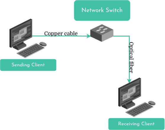
Like any other type of computer data, a packet is composed of a long series of bits. Each bit in a packet must be moved all the way to its destination. However, the physical media over which they must travel are diverse. Sometimes, it will be optical fiber, other times it will be copper wire, or even radio waves! It’s no wonder the methods for transmitting the bits vary depending on the physical medium.
Moving a packet’s bits from one physical medium to another is the network switch’s job. Along its route, a packets will no doubt pass through several switches. Le switch receives the packet over one type of physical transport medium and transfers it over another physical medium to the next node on the route.
Routers
But all of the packets travelling via the Internet aren’t all going to the same destination! Therefore, there are intersections in the network through which the packet must be routed. That’s the role of a more sophisticated type of switch: a router. Just like the network switch, the router is able to move a packet from one physical medium to another, but that is not all. A router is usually connected to several different segments and has the ability to determine which direction to send a packet depending on its destination.
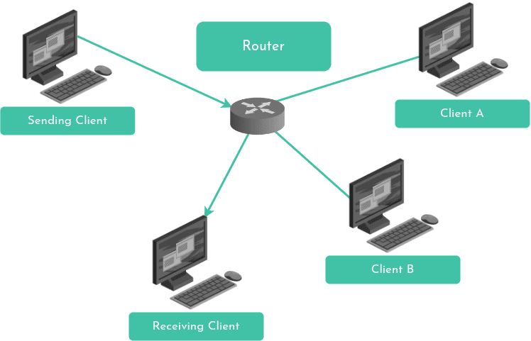
Below, we will take a closer look at how a router determines which direction to send a packet to, thanks to its forwarding table. But first, we must understand network interfaces.
Network Interfaces
Every device - client, server, router - that is connected to the Internet has at least one network interface. It’s the network card that acts as a bridge between the device and the physical medium connected to the rest of the network: where we’d plug our Ethernet cable, for instance. The interface is a sort of border between the device and the network at large. A client typically only has one interface since it only has one network connection. However, a router usually has many: one for each of its network connections.
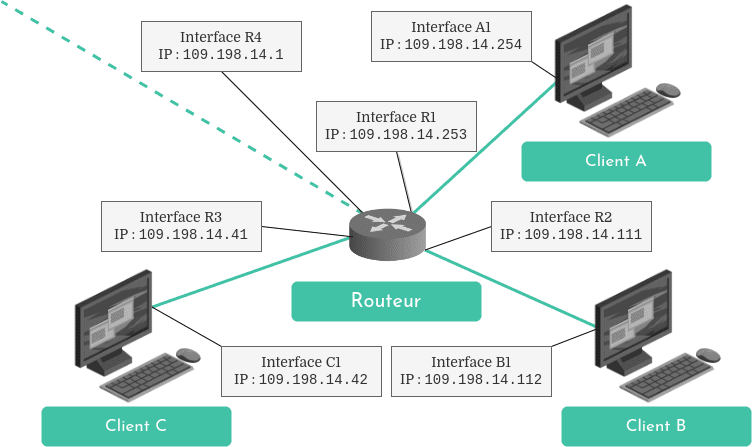
On the Internet, an IP address is associated with each interface, which allows it to be uniquely identified. So what is an IP address, particularly an IPv4 address?
What is an IPv4 Address?
As we’ve just seen, an IP address identifies a device’s network interface, not the device itself. To understand what an IPv4 address is, let’s start by taking a look at what “IP” means.
What is IP?
In the previous article about the Internet’s architecture, we had the chance to examine the different protocol layers a data packet has to go through in order to be sent and received. Addressing and routing is the main role of the network layer’s IP protocol.
IP (" I nternet P rotocol") is charged with routing packets towards their destinations. This protocol defines IP addresses which uniquely identify each connected host. In addition, it runs in all hosts (clients and servers) and all routers on the Internet.
In the sending host, IP adds a header to each packet to be sent. The header is a datagram which contains, among other things, the IP addresses of the sending and destination hosts. In a router, IP maintains a forwarding table and executes routing algorithms to analyze packets’ destination addresses in order to determine which directions to transfer them.
The Anatomy of an IPv4 Address
An IPv4 address is an address of the Internet Protocol version 4. These are the most common on the Internet today. However, a new version of the Internet Protocol also exists : IPv6. And with it, a new addressing system, which we will touch on at the end of this article.
An IPv4 address is a 32 bit (4 octet) integer. It’s represented by four positive numbers separated with dots. Each one of these numbers represent an octet (8 bits). As an example, let’s take an arbitrary address: 198.42.214.5. The number 198 is the base 10 equivalent of the first octet in the address; 42 represents the second octet, and so on. Let’s look at this address in binary:
Decimal notation198``42``214``5Binary notation11000110``00101010``11010110``00000101
With this limitation of 32 bits, IPv4 addresses aren’t infinite. The smallest possible address is 0.0.0.0 and the largest is 255.255.255.255:
Decimal         : Binary
0.0.0.0         : 00000000 00000000 00000000 00000000
255.255.255.255 : 11111111 11111111 11111111 11111111
A Router’s Forwarding Table
A router’s function is to examine incoming packets’ headers and read the destination address in order to be able to transfer it to its most appropriate output link. IP maintains a forwarding table (or a Forwarding Information Base, FIB) inside the router. Its routing algorithm uses it to determine which way to send the packet. As an example, let’s imagine routing with 4 bit IP addresses:
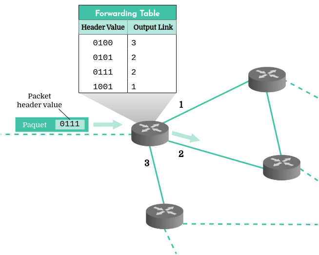
In this example, the router reads the incoming packet’s header and checks its forwarding table to determine that it should transfer it to its interface number 2.
However, there are about 4 billion 32 bit IPv4 addresses. Clearly, a router with a forwarding table containing 4 billion entries would be extremely slow and inefficient, event with a very optimized routing algorithm! Wouldn’t it be more convenient to simply read the first few bits of the address to know where to send a packet? Exactly! That’s one of the advantages that comes with the concept of subnetworks.
Subnet Masks
The first few bits of an IP address represent the subnetwork (subnet) which the device is a part of, and the following bits identify the interface itself. This way, a router usually only has to look at the network part of the address to know where to forward an incoming packet. To isolate the bits representing the subnetwork, a router uses a subnet mask. So how many bits represent the subnet portion of the address? The answer to this is not as simple as it may seem…
Classful IP Addressing
We understood, in the article about the Internet’s architecture, that the Internet is a network made of many subnetworks. IP addresses are assigned by range depending on the size of the subnetwork. Originally, address ranges were categorized into several classes: A for the largest networks, B for medium-sized networks and C for the smallest networks. So the 8, 16 or 24 first bits of the IPv4 address represented the subnetwork, and the following bits identified the host within that subnet.
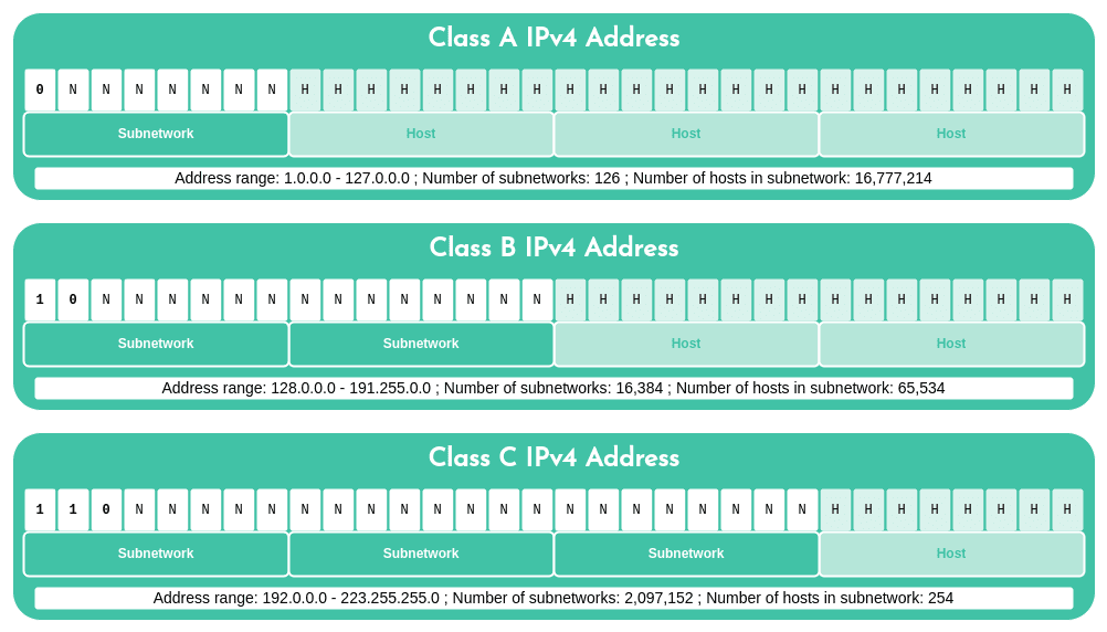
In order to isolate the bits representing the subnetwork, it was necessary to first identify its class. If the first bit was 0, the address belonged to a class A network; if the first two bits were 1 and 0, the address was class B; if the first three were 110, then it belonged to class C. Then, we could apply the appropriate subnet mask as well as the bitwise AND operation to identify the subnetwork. For example, with a class B address:
IP        : 10100111 00101101 11000110 00000010 : 167.45.198.2
B Mask    : 11111111 11111111 00000000 00000000 : 255.255.0.0
Bitwise & : 10100111 00101101 00000000 00000000 : 167.45.0.0
However, in the 1990s, having 1, 2 or 3 octets representing the subnet in an address proved to be too rigid of a system to support the growing number of small to medium organization networks. A class C subnet could only accommodate 254 hosts: too few for most organizations. But a class B subnet, which could support up to 65,354 hosts, was much too big! Yet with this system, an organization wishing to connect 2,000 hosts would get a class B subnet. Cases like this represented a loss of 63,000 addresses that could not be used by any other organizations.
Therefore, this classful IPv4 addressing method was soon abandoned in favor of a classless addressing system which is still in use today : CIDR.
Classless IP Addressing: CIDR
Classless Inter-Domain Routing ( CIDR) generalized the notion of subnetworks by making it more flexible. In this system, the subnet part of the address is not fixed as in the class method above. CIDR subnet masks can be of varying lengths, which allows for a much more efficient use of IP address space.
Since the subnet mask can no longer be deduced from the IP address itself, CIDR introduced a new notation to indicate the number of bits representing the subnetwork. The four-octet IPv4 address may be followed by a slash, and then the number of subnetwork bits. For example, 128.42.42.201/28 indicates that the 28 first bits of the address represent the subnetwork:
IP        : 10000000 00101010 00101010 11001001 : 128.42.42.201
/28 Mask  : 11111111 11111111 11111111 11110000 : 255.255.255.240
Bitwise & : 10000000 00101010 00101010 11000000 : 128.42.42.192
The formula to determine the number of possible addresses within a subnetwork is 2address length - mask. This means that there are 232-28 = 24 = 16 possible IPv4 addresses in this 28-bit subnet range:
IP       : 10000000 00101010 00101010 11001001 : 128.42.42.201
/28 Mask : 11111111 11111111 11111111 11110000 : 255.255.255.240
IP min   : 10000000 00101010 00101010 11000000 : 128.42.42.192
IP max   : 10000000 00101010 00101010 11001111 : 128.42.42.207
In this way, an Internet Service Provider may receive a /19 bloc, meaning 232-19 = 213 = 8,192 IPv4 addresses. It can then break this block down into subnetworks of varying sizes depending on its client’s needs. For example, for one small organization requiring 200 connected hosts, it could provide a /24 subnet (232-24 = 28 = 256 addresses). To a larger company requiring 2,000 hosts, it could allocate another /20 subnet (232-21 = 211 = 2,048 addresses).
Subnet Masks and Routing
But how do these CIDR subnet masks work to help route a packet to its destination, in practice? To understand this, let’s map out a small fictitious part of Internet.
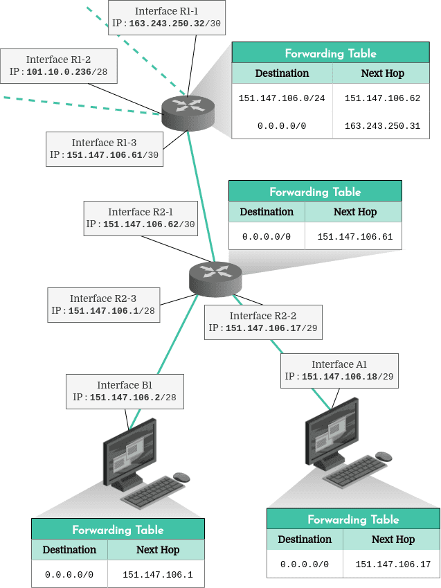
The first thing we might notice here is that each client and router has a forwarding table which informs it where to send packets. The router at the top of the diagram has two entries in its forwarding table. The first entry indicates that all incoming packets with addresses starting with the first 24 bits being 151.147.106.x must be sent to the second router’s interface with the address 151.147.106.62. That’s the “next hop” on the route to their destination. The second entry in this same forwarding table indicates that by default, all packets should be sent to 163.243.250.31 (another router connected to the R1-1 interface which doesn’t appear on this diagram), whatever their destination ( 0.0.0.0/0).
There are three distinct subnets in this diagram:
- The 30-bit subnet
151.147.106.60, which contains the two routers’ interfaces, R1-3 (151.147.106.61) and R2-1 (151.147.106.62). - A 28-bit subnet,
151.147.106.0, containing the router’s R2-3 interface (151.147.106.1) and the client’s B1 interface (151.147.106.2). The addresses inside this subnetwork must be between151.147.106.1and151.147.106.14. - And a 29-bit subnet,
151.147.106.16, which contains the router’s R2-2 interface (151.147.106.17) and the client’s A1 interface (151.147.106.18). The interfaces inside this subnet must have addresses between151.147.106.16and151.147.106.22.
Of course, subnets should not overlap. For example, we couldn’t assign the address 151.147.106.3 to the R2-2 interface, since that address is part of the R2-3 interface’s subnet.
Reserved IPv4 Addresses
About 600 million IPv4 addresses are reserved for specific uses and cannot be assigned. These addresses are used, among other things, for multicast traffic, to maintain router tables, to translate IPv4 to IPv6, or to provide unrestricted address space for private networks.
| Address Blocks | Range of Addresses | Number of Addresses | Use |
|---|---|---|---|
| 0.0.0.0/8 | 0.0.0.0 – 0.255.255.255 | 16 777 216 | Software |
| 10.0.0.0/8 | 10.0.0.0 – 10.255.255.255 | 16 777 216 | Private network: local communications |
| 100.64.0.0/10 | 100.64.0.0 – 100.127.255.255 | 4 194 304 | Private network: ISP communications |
| 127.0.0.0/8 | 127.0.0.0 – 127.255.255.255 | 16 777 216 | Host: loopback addresses for localhost |
| 169.254.0.0/16 | 169.254.0.0 – 169.254.255.255 | 65 536 | Subnet: local communications between two hosts on a single link |
| 172.16.0.0/12 | 172.16.0.0 – 172.31.255.255 | 1 048 576 | Private network: local communications |
| 192.0.0.0/24 | 192.0.0.0 – 192.0.0.255 | 256 | Private network: IETF protocol assignments |
| 192.0.2.0/24 | 192.0.2.0 – 192.0.2.255 | 256 | Documentation: TEST-NET-1 |
| 192.88.99.0/24 | 192.88.99.0 – 192.88.99.255 | 256 | Reserved: 6to4 relay |
| 192.168.0.0/16 | 192.168.0.0 – 192.168.255.255 | 65 536 | Private network: local communications |
| 198.18.0.0/15 | 198.18.0.0 – 198.19.255.255 | 131 072 | Private network: bench-marking between two connected subnets |
| 198.51.100.0/24 | 198.51.100.0 – 198.51.100.255 | 256 | Documentation: TEST-NET-2 |
| 203.0.113.0/24 | 203.0.113.0 – 203.0.113.255 | 256 | Documentation: TEST-NET-3 |
| 224.0.0.0/4 | 224.0.0.0 – 239.255.255.255 | 268 435 456 | Reserved: IPv4 multicast |
| 233.252.0.0/24 | 233.252.0.0 – 233.252.0.255 | 256 | Documentation: MCAST-TEST-NET |
| 240.0.0.0/4 | 240.0.0.0 – 255.255.255.254 | 268 435 455 | Reserved: for future use |
| 255.255.255.255/32 | 255.255.255.255 | 1 | Subnet: limited broadcast destination address |
As we can see in this table, come addresses are reserved for technical purposes (testing, documentation, protocol assignments). But what does “private network” mean, exactly?
Public vs Private Addresses
A public address is assigned to a router by an Internet Service Provider, and allows communications over the Internet. So with a public address, one can send and receive packets from anywhere on the Internet.
A private address is assigned by a router to each device connected to it. This private address allows communication within the same subnetwork, for example between devices connected to the same WiFi network. Of course, a device cannot use its private address to send or receive packets from outside its network. This private address system saves IPv4 address space since several devices may have the same private address as long as they aren’t on the same subnet.
Network Addresses and Broadcast Addresses
Network and broadcast addresses do not appear on the list of reserved addresses above. However, they should generally not be used either.
Each subnetwork address range starts with the address of the network itself. For example, the address 130.200.189.45/24 is part of an address block starting at 130.200.189.0/24. This address is therefore considered the network address and cannot be assigned to an interface.
The same goes for the last address in a block. If we go back to the previous example, the last address in that block is 130.200.189.255/24. This address is called the broadcast address because a packet sent to it is transferred to all interfaces in the subnetwork. For this reason, broadcast addresses cannot be assigned to a device interface either.
Curbing the IPv4 Address Shortage
A 32-bit length means that there are around 4 billion IPv4 addresses. That’s a lot! Yet it isn’t enough for all devices connected to this global network. 4 billion, that’s only half of the human population. And more and more citizens of developing countries are using the Internet. Further, a growing number of objects are now also connected to the Internet: watches, cars, smart cities, seismic monitoring or home security systems… In short, the Internet of Things.
Foreseeing increasing Internet usage in the 1990s, the Internet Engineering Task Force focused on a successor to IPv4, which could offer many more addresses…
IPv6 Addresses
IP’s version 6 dramatically increases the length of IP addresses from 32 to 128 bits. 128 bits means a capacity of over 340 sextillion addresses. That’s enough for each grain of sand on Earth to have its own IP address and more!
An IPv6 address is represented with hexadecimal numbers, with 8 groups of 16 bits (2 octets), separated by a colon “:”:
2001:0db8:0000:85a3:0000:0000:ac1f:8001
We can shorten the notation by removing some non-significant zeros:
2001:db8:0:85a3:0:0:ac1f:8001
And if there are several consecutive null 16-bit groups, we can further abbreviate, keeping only the “:” on each side of the omitted sequence, like this:
2001:db8:0:85a3::ac1f:8001
CIDR subnet masks and notations also apply to IPv6 addresses.
Since it is inconceivable to turn off the entire Internet for the time it would take to update all hosts and routers to the new IP version, IPv6 is progressively deployed. IPv6 is backward-compatible with IPv4, but the opposite is not necessarily true. Some routers and hosts are incapable of running IPv6. Until they can be replaced, an IPv6 packet that must travel through an incompatible router can temporarily disguise itself as IPv4 before being restored to IPv6 further along its route, if possible.
A little tip to share, a nagging question to ask, or a strange discovery to discuss about IPv4 addresses, routing or subnet masks? I’d love to read and respond to it all in the comments. Happy coding !
Sources and Further Reading
- Kurose, J. F., Ross, K. W., 2013, Computer Networking: A Top Down Approach, Sixth Edition, Chapter 1: Computer Networks and the Internet, pp. 1-82.
- Wikipedia, Subnetwork [Wikipedia]
- Wikipedia, IPv4 [Wikipedia]
- RFC editor, Special-Purpose IP Address Registries (2013) [rfc-editor.org]